Page 282 - Fair, Geyer, and Okun's Water and wastewater engineering : water supply and wastewater removal
P. 282

JWCL344_ch07_230-264.qxd  8/2/10  8:44 PM  Page 242


                    242  Chapter 7  Water Distribution Systems: Modeling and Computer Applications

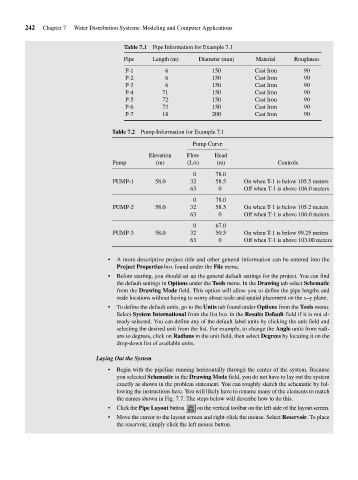
                                                  Table 7.1  Pipe Information for Example 7.1

                                                  Pipe     Length (m)    Diameter (mm)    Material    Roughness
                                                  P-1         6              150          Cast Iron      90
                                                  P-2         6              150          Cast Iron      90
                                                  P-3         6              150          Cast Iron      90
                                                  P-4         71             150          Cast Iron      90
                                                  P-5         72             150          Cast Iron      90
                                                  P-6         73             150          Cast Iron      90
                                                  P-7         18             200          Cast Iron      90

                                              Table 7.2  Pump Information for Example 7.1

                                                                       Pump Curve
                                                          Elevation  Flow    Head
                                              Pump          (m)      (L/s)    (m)                Controls
                                                                       0      78.0
                                              PUMP-1       58.0       32      58.5    On when T-1 is below 105.5 meters
                                                                      63       0      Off when T-1 is above 106.0 meters
                                                                       0      78.0
                                              PUMP-2       58.0       32      58.5    On when T-1 is below 105.2 meters
                                                                      63       0      Off when T-1 is above 106.0 meters
                                                                       0      67.0
                                              PUMP-3       58.0       32      50.5    On when T-1 is below 99.25 meters
                                                                      63       0      Off when T-1 is above 103.00 meters


                                             •  A more descriptive project title and other general information can be entered into the
                                                Project Properties box found under the File menu.
                                             •  Before starting, you should set up the general default settings for the project. You can find
                                                the default settings in Options under the Tools menu. In the Drawing tab select Schematic
                                                from the Drawing Mode field. This option will allow you to define the pipe lengths and
                                                node locations without having to worry about scale and spatial placement on the x–y plane.
                                             •  To define the default units, go to the Units tab found under Options from the Tools menu.
                                                Select System International from the list box in the Results Default field if it is not al-
                                                ready selected. You can define any of the default label units by clicking the unit field and
                                                selecting the desired unit from the list. For example, to change the Angle units from radi-
                                                ans to degrees, click on Radians in the unit field, then select Degrees by locating it on the
                                                drop-down list of available units.

                                          Laying Out the System
                                             •  Begin with the pipeline running horizontally through the center of the system. Because
                                                you selected Schematic in the Drawing Mode field, you do not have to lay out the system
                                                exactly as shown in the problem statement. You can roughly sketch the schematic by fol-
                                                lowing the instructions here. You will likely have to rename many of the elements to match
                                                the names shown in Fig. 7.7. The steps below will describe how to do this.
                                             •  Click the Pipe Layout button   on the vertical toolbar on the left side of the layout screen.
                                             •  Move the cursor to the layout screen and right-click the mouse. Select Reservoir. To place
                                                the reservoir, simply click the left mouse button.
   277   278   279   280   281   282   283   284   285   286   287