Page 353 - Fair, Geyer, and Okun's Water and wastewater engineering : water supply and wastewater removal
P. 353

JWCL344_ch09_297-332.qxd  8/2/10  9:54 PM  Page 313


                                                                            9.3 Theory of Backflow and Backsiphonage  313

                                                   Valve open


                                                              Submerged inlet


                                                  Valve open

                                                           Closed supply
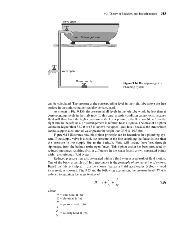
                                                                                        Figure 9.14 Backsiphonage in a
                                                                                        Plumbing System


                                         can be calculated. The pressure at the corresponding level in the right tube above the free
                                         surface in the right container can also be calculated.
                                             As shown in Fig. 9.13b, the pressure at all levels in the left tube would be less than at
                                         corresponding levels in the right tube. In this case, a static condition cannot exist because
                                         fluid will flow from the higher pressure to the lower pressure; the flow would be from the
                                         right tank to the left tank. This arrangement is referred to as a siphon. The crest of a siphon
                                         cannot be higher than 33.9 ft (10.3 m) above the upper liquid level, because the atmosphere
                                         cannot support a column of water greater in height than 33.9 ft (10.3 m).
                                             Figure 9.14 illustrates how this siphon principle can be hazardous in a plumbing sys-
                                         tem. If the supply valve is closed, the pressure in the line supplying the faucet is less than
                                         the pressure in the supply line to the bathtub. Flow will occur, therefore, through
                                         siphonage, from the bathtub to the open faucet. This siphon action has been produced by
                                         reduced pressures resulting from a difference in the water levels at two separated points
                                         within a continuous fluid system.
                                             Reduced pressure may also be created within a fluid system as a result of fluid motion.
                                         One of the basic principles of fluid mechanics is the principle of conservation of energy.
                                         Based on this principle, it can be shown that as a fluid accelerates (velocity head
                                         increases), as shown in Fig. 9.15 and the following expression, the pressure head (P> ) is
                                         reduced to maintain the same total head:
                                                                              P    v 2
                                                                      H = z +    +                            (9.5)
                                                                              g    2g
                                         where
                                               H   total head, ft (m)
                                               Z   elevation, ft (m)
                                               P
                                                   pressure head, ft (m)
                                               g
                                              v 2
                                                   velocity head, ft (m).
                                              2g
   348   349   350   351   352   353   354   355   356   357   358