
Page 357 - Fair, Geyer, and Okun's Water and wastewater engineering : water supply and wastewater removal
P. 357
JWCL344_ch09_297-332.qxd 8/2/10 9:54 PM Page 317
9.4 Methods and Devices for the Prevention of Backflow and Backsiphonage 317
the American Society of Sanitary Engineers (ASSE), the American Water Works
Association (AWWA), and the University of California Foundation for Cross-Connection
Control and Hydraulic Research.
9.4.1 Air Gap
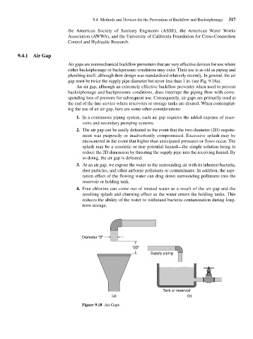
Air gaps are nonmechanical backflow preventers that are very effective devices for use where
either backsiphonage or backpressure conditions may exist. Their use is as old as piping and
plumbing itself, although their design was standardized relatively recently. In general, the air
gap must be twice the supply pipe diameter but never less than 1 in. (see Fig. 9.18a).
An air gap, although an extremely effective backflow preventer when used to prevent
backsiphonage and backpressure conditions, does interrupt the piping flow with corre-
sponding loss of pressure for subsequent use. Consequently, air gaps are primarily used at
the end of the line service where reservoirs or storage tanks are desired. When contemplat-
ing the use of an air gap, here are some other considerations:
1. In a continuous piping system, each air gap requires the added expense of reser-
voirs and secondary pumping systems.
2. The air gap can be easily defeated in the event that the two-diameter (2D) require-
ment was purposely or inadvertently compromised. Excessive splash may be
encountered in the event that higher than anticipated pressures or flows occur. The
splash may be a cosmetic or true potential hazard—the simple solution being to
reduce the 2D dimension by thrusting the supply pipe into the receiving funnel. By
so doing, the air gap is defeated.
3. At an air gap, we expose the water to the surrounding air with its inherent bacteria,
dust particles, and other airborne pollutants or contaminants. In addition, the aspi-
ration effect of the flowing water can drag down surrounding pollutants into the
reservoir or holding tank.
4. Free chlorine can come out of treated water as a result of the air gap and the
resulting splash and churning effect as the water enters the holding tanks. This
reduces the ability of the water to withstand bacteria contamination during long-
term storage.
Diameter “D”
“2D”
Supply piping
Tank or reservoir
(a) (b)
Figure 9.18 Air Gaps