
Page 360 - Fair, Geyer, and Okun's Water and wastewater engineering : water supply and wastewater removal
P. 360
JWCL344_ch09_297-332.qxd 8/2/10 9:54 PM Page 320
320 Chapter 9 Cross-Connection Control
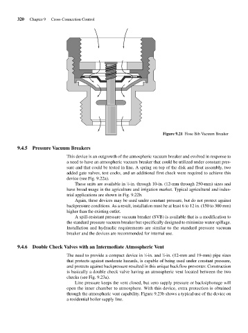
Figure 9.21 Hose Bib Vacuum Breaker
9.4.5 Pressure Vacuum Breakers
This device is an outgrowth of the atmospheric vacuum breaker and evolved in response to
a need to have an atmospheric vacuum breaker that could be utilized under constant pres-
sure and that could be tested in line. A spring on top of the disk and float assembly, two
added gate valves, test cocks, and an additional first check were required to achieve this
device (see Fig. 9.22a).
These units are available in ⁄2-in. through 10-in. (12-mm through 250-mm) sizes and
1
have broad usage in the agriculture and irrigation market. Typical agricultural and indus-
trial applications are shown in Fig. 9.22b.
Again, these devices may be used under constant pressure, but do not protect against
backpressure conditions. As a result, installation must be at least 6 to 12 in. (150 to 300 mm)
higher than the existing outlet.
A spill-resistant pressure vacuum breaker (SVB) is available that is a modification to
the standard pressure vacuum breaker but specifically designed to minimize water spillage.
Installation and hydraulic requirements are similar to the standard pressure vacuum
breaker and the devices are recommended for internal use.
9.4.6 Double Check Valves with an Intermediate Atmospheric Vent
The need to provide a compact device in ⁄2-in. and ⁄4-in. (12-mm and 19-mm) pipe sizes
1
3
that protects against moderate hazards, is capable of being used under constant pressure,
and protects against backpressure resulted in this unique backflow preventer. Construction
is basically a double check valve having an atmospheric vent located between the two
checks (see Fig. 9.23a).
Line pressure keeps the vent closed, but zero supply pressure or backsiphonage will
open the inner chamber to atmosphere. With this device, extra protection is obtained
through the atmospheric vent capability. Figure 9.23b shows a typical use of the device on
a residential boiler supply line.