
Page 364 - Fair, Geyer, and Okun's Water and wastewater engineering : water supply and wastewater removal
P. 364
JWCL344_ch09_297-332.qxd 8/2/10 9:54 PM Page 324
324 Chapter 9 Cross-Connection Control
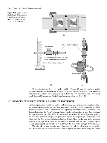
Figure 9.26 (a) Residential
Dual Check, (b) Residential
Installation and (c) Copper
Horn. Conversion factor:
1 1 in. 25.4 mm
(a)
Residential dual check
Water meter
1
1 4 ˝ meter thread female inlet with
1˝ NPT thread female union outlet
Water meter
(b) (c)
This device is sized for ⁄2-, ⁄4-, and 1-in (12-, 19-, and 25-mm) service lines and is
3
1
installed immediately downstream of the water meter. The use of plastic check modules
and elimination of test cocks and gate valves keep the cost reasonable while providing
good, dependable protection. Typical installations are shown in Fig. 9.26b.
9.5 REDUCED PRESSURE PRINCIPLE BACKFLOW PREVENTER
Maximum protection is achieved against backsiphonage and backpressure conditions utiliz-
ing reduced pressure principle backflow preventers. These devices are essentially modified
double check valves with an atmospheric vent capability placed between the two checks and
designed such that this “zone” between the two checks is always kept at least 2 psi less than
the supply pressure (see Fig. 9.27). With this design criterion, the reduced pressure princi-
ple backflow preventer can provide protection against backsiphonage and backpressure
when both the first and second checks become fouled. They can be used under constant
pressure and at high hazard installations. They are furnished with test cocks and gate valves
3
to enable testing and are available in ⁄4-in. through 10-in. (19-mm through 250-mm) sizes.
The principles of operation of a reduced pressure principle backflow preventer are as fol-
lows: Flow from the left enters the central chamber against the pressure exerted by the loaded