
Page 205 - Fiber Bragg Gratings
P. 205
182 Chapter 4 Theory of Fiber Bragg Gratings
Figure 4.31: The concatenation of several short reflection gratings with con-
stant parameters to form a composite grating. The phase <f> N is the phase of the
grating in each section.
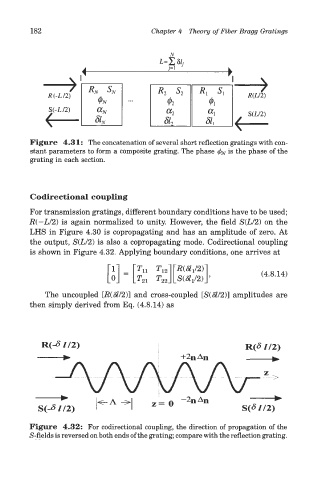
Codirectional coupling
For transmission gratings, different boundary conditions have to be used;
.R(-L/2) is again normalized to unity. However, the field S(L/2) on the
LHS in Figure 4.30 is copropagating and has an amplitude of zero. At
the output, S(L/2) is also a copropagating mode. Codirectional coupling
is shown in Figure 4.32. Applying boundary conditions, one arrives at
The uncoupled [R($/2)] and cross-coupled [S(Sl/2)] amplitudes are
then simply derived from Eq. (4.8.14) as
Figure 4.32: For Codirectional coupling, the direction of propagation of the
S-fields is reversed on both ends of the grating; compare with the reflection grating.