
Page 390 - Fiber Bragg Gratings
P. 390
8.2 Static and dynamic properties of FGLs 367
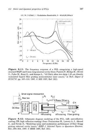
Figure 8.11: The frequency response of a FGL comprising a high-speed
strained MQW and 8-mm-long external cavity (from: Paoletti P., Meliga M., Oliveti
G., Puleo M., Rossi G., and Senepa L., "10 Gbit/s ultra low chirp 1.55 /um directly
modulated hygrid fiber grating semiconductor laser source," in Tech. Digest of
ECOC'97, pp. 107-110, 1997. © IEE 1997, Ref. [32]).
Figure 8.12: Schematic diagram modeling of the FGL. (AR: antireflective
coating; HR: high reflective coating) (from: Premaratne M., Lowery A. J., Ahmed
Z., and Novak D., "Modelling noise and modulation performance of fiber Bragg
grating external cavity lasers," IEEE J. Selected Topics in Quantum Electron.
3(2), 290-303, 1997. © IEEE 1997, Ref. [33]).