
Page 393 - Fiber Bragg Gratings
P. 393
370 Chapter 8 Fiber Grating Lasers and Amplifiers
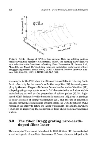
Figure 8.14: Change of RPSS vs bias current. Note the splitting position
variation with bias current (4-GHz external cavity). The splitting may be reduced
by a reduction in the front facet reflectivity (from: Premaratne M., Lowery A. J.,
Ahmed Z., and Novak D., "Modelling noise and modulation performance of fiber
Bragg grating external cavity lasers," IEEE J. Selected Topics in Quantum Elec-
tron. 3(2), 290-303, 1997. © IEEE 1997, Ref. [33]).
ous designs for the FGL show the alternatives available in reducing front-
facet reflectivity by the use of a reflective amplifier [24], increasing cou-
pling by the use of hyperbolic lenses formed on the ends of the fiber [19],
chirped gratings to promote smooth L-I characteristics and allow stable
mode-locking as well as the generation of soliton pulses [17,18], high-
speed MQW designs for wide-bandwidth operation [32], plug-in gratings
to allow selection of lasing wavelengths [26], and the use of coherence
collapse for the injection locking of pump lasers [21]. The benefits of FGLs
remain in the ability to define the lasing wavelength [26] and the low chirp
[15,28,32] in improving the utilization of laser chips from manufactured
wafers.
8.3 The fiber Bragg grating rare-earth-
doped fiber laser
The concept of fiber lasers dates back to 1960. Snitzer [41] demonstrated
a rod waveguide of smallish dimensions (0.5-mm diameter) doped with