
Page 399 - Fiber Bragg Gratings
P. 399
376 Chapter 8 Fiber Grating Lasers and Amplifiers
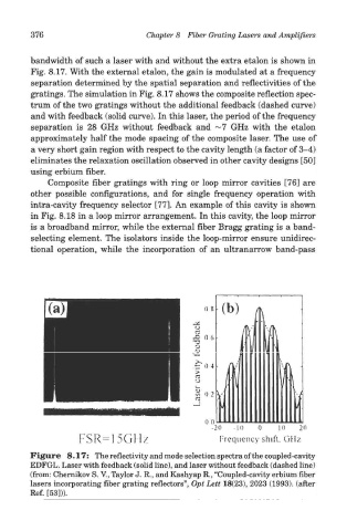
bandwidth of such a laser with and without the extra etalon is shown in
Fig. 8.17. With the external etalon, the gain is modulated at a frequency
separation determined by the spatial separation and reflectivities of the
gratings. The simulation in Fig. 8.17 shows the composite reflection spec-
trum of the two gratings without the additional feedback (dashed curve)
and with feedback (solid curve). In this laser, the period of the frequency
separation is 28 GHz without feedback and ~7 GHz with the etalon
approximately half the mode spacing of the composite laser. The use of
a very short gain region with respect to the cavity length (a factor of 3-4)
eliminates the relaxation oscillation observed in other cavity designs [50]
using erbium fiber.
Composite fiber gratings with ring or loop mirror cavities [76] are
other possible configurations, and for single frequency operation with
intra-cavity frequency selector [77]. An example of this cavity is shown
in Fig. 8.18 in a loop mirror arrangement. In this cavity, the loop mirror
is a broadband mirror, while the external fiber Bragg grating is a band-
selecting element. The isolators inside the loop-mirror ensure unidirec-
tional operation, while the incorporation of an ultranarrow band-pass
Figure 8.17: The reflectivity and mode selection spectra of the coupled-cavity
EDFGL. Laser with feedback (solid line), and laser without feedback (dashed line)
(from: Chernikov S. V., Taylor J. R., and Kashyap R., "Coupled-cavity erbium fiber
lasers incorporating fiber grating reflectors", Opt Lett 18(23), 2023 (1993). (after
Ref. [53])).