
Page 405 - Fiber Bragg Gratings
P. 405
382 Chapter 8 Fiber Grating Lasers and Amplifiers
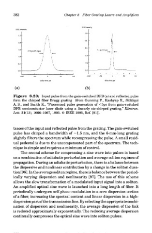
Figure 8.23: Input pulse from the gain-switched DFB (a) and reflected pulse
form the chirped fiber Bragg grating (from Gunning P., Kashyap R., Siddiqui
A. S., and Smith K., "Picosecond pulse generation of <5ps from gain-switched
DFB semiconductor laser diode using a linearly ste-chirped grating," Electron.
Lett. 31(13), 1066-1067, 1995. © IEEE 1995, Ref. [91]).
traces of the input and reflected pulse from the grating. The gain-switched
pulse has chirped a bandwidth of —1.5 nm, and the 6-mm-long grating
slightly filters the spectrum while recompressing the pulse. A small resid-
ual pedestal is due to the uncompensated part of the spectrum. The tech-
nique is simple and requires a minimum of control.
The second scheme for compressing a sine wave into pulses is based
on a combination of adiabatic perturbation and average soliton regimes of
propagation. During an adiabatic perturbation, there is a balance between
the dispersive and nonlinear contribution by a change in the soliton dura-
tion [96]. In the average soliton regime, there is balance between the period-
ically varying dispersion and nonlinearity [97]. The use of this scheme
allows the slow transformation of a modulated input signal into a soliton.
An amplified optical sine wave is launched into a long length of fiber. It
periodically undergoes self-phase modulation in a zero-dispersion section
of a fiber, increasing the spectral content and linear dispersion in a high-
dispersion part of the transmission line. By selecting the appropriate combi-
nation of dispersion and nonlinearity, the average dispersion of the link
is reduced approximately exponentially. The reducing average dispersion
continually compresses the optical sine wave into soliton pulses.