
Page 412 - Fiber Bragg Gratings
P. 412
8.8 Gain-flattening and clamping in fiber amplifiers 389
With this information, the filter is fabricated with the amplifier at its
operating inversion level, allowing live gain tailoring. In this instance up
to nine individual STGs were written to match the variation in the gain.
Each grating can be — 1 mm long, making the entire gain equalization
filter to be less than 10 mm. Such a filter may be written using a single
phase mask appropriately designed to give the desired loss at each wave-
length, by scaling the length of each grating or with an appropriate ampli-
tude shading [123]. A distinct advantage of the STG is that the
uncompensated temperature sensitivity of the loss spectrum is similar
to that for Bragg grating, making the filter intrinsically stable. With
temperature compensation as with Bragg gratings, the variation in the
loss spectrum may be eliminated altogether over the required operating
temperature range.
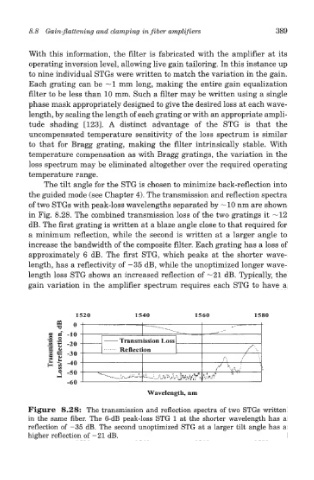
The tilt angle for the STG is chosen to minimize back-reflection into
the guided mode (see Chapter 4). The transmission and reflection spectra
of two STGs with peak-loss wavelengths separated by —10 nm are shown
in Fig. 8.28. The combined transmission loss of the two gratings it —12
dB. The first grating is written at a blaze angle close to that required for
a minimum reflection, while the second is written at a larger angle to
increase the bandwidth of the composite filter. Each grating has a loss of
approximately 6 dB. The first STG, which peaks at the shorter wave-
length, has a reflectivity of -35 dB, while the unoptimized longer wave-
length loss STG shows an increased reflection of —21 dB. Typically, the
gain variation in the amplifier spectrum requires each STG to have a
Figure 8.28: The transmission and reflection spectra of two STGs written
in the same fiber. The 6-dB peak-loss STG 1 at the shorter wavelength has a
reflection of —35 dB. The second unoptimized STG at a larger tilt angle has a
higher reflection of -21 dB.