
Page 416 - Fiber Bragg Gratings
P. 416
8.8 Gain-flattening and clamping in fiber amplifiers 393
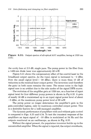
Figure 8.31: Output spectra of all-optical AGC amplifier, lasing at 1520 nm
[134].
the cavity loss at 2.5 dB, single pass. The pump power in the fiber from
a 1480-nm diode laser was approximately 80 mW.
Figure 8.31 shows the compensatory effect of the control laser in the
broadband output spectra. As the input signal is increased to —2 dBm
from the small signal level (-30 dBm), there is more than 10 dB of
reduction in the residual laser output power. The inversion (and therefore
the gain) in both cases remains the same. The excess noise in the high
signal case is an artifact due to the side modes of the signal DFB source.
The evolution of the amplifier gain at 1550 nm, as a function of input
signal level for four different pump powers is shown in Fig 8.32. A gain
of nearly 16 dB is maintained up to an input signal power level of about
—5 dBm, at the maximum pump power level of 80 mW.
The pump power no longer determines the amplifier's gain in the
gain-controlled regime, only its maximum controlled output power. This
is a desirable feature for a well-managed amplifier.
The dynamic performance of amplifiers with and without gain control
is compared in Figs. 8.33 and 8.34. To test the transient response of the
amplifiers an input signal of -10 dBm is modulated at 54 Hz and the
outputs monitored on an oscilloscope, as shown in Fig. 8.33.
Without the signal present, the population inversion builds up in the
uncontrolled amplifier. When the signal is injected, the output overshoots,