
Page 421 - Fiber Bragg Gratings
P. 421
398 Chapter 8 Fiber Grating Lasers and Amplifiers
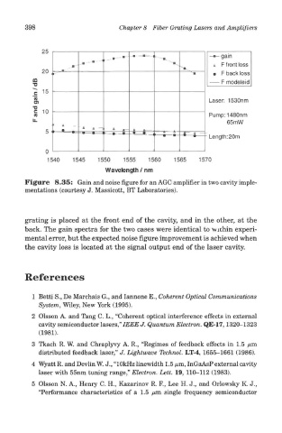
Figure 8.35: Gain and noise figure for an AGC amplifier in two cavity imple-
mentations (courtesy J. Massicott, BT Laboratories).
grating is placed at the front end of the cavity, and in the other, at the
back. The gain spectra for the two cases were identical to wuhin experi-
mental error, but the expected noise figure improvement is achieved when
the cavity loss is located at the signal output end of the laser cavity.
References
1 Betti S., De Marchais G., and lannone E., Coherent Optical Communications
System, Wiley, New York (1995).
2 Olsson A. and Tang C. L., "Coherent optical interference effects in external
cavity semiconductor lasers," IEEE J. Quantum Electron. QE-17,1320-1323
(1981).
3 Tkach R. W. and Chraplyvy A. R., "Regimes of feedback effects in 1.5 /am
distributed feedback laser," J. Lightwave Technol. LT-4, 1655-1661 (1986).
4 Wyatt R. and Devlin W. J., "10kHz linewidth 1.5 /urn, InGaAsP external cavity
laser with 55nm tuning range," Electron. Lett. 19, 110-112 (1983).
5 Olsson N. A., Henry C. H., Kazarinov R. F., Lee H. J., and Orlowsky K. J.,
"Performance characteristics of a 1.5 /urn single frequency semiconductor