
Page 415 - Fiber Bragg Gratings
P. 415
392 Chapter 8 Fiber Grating Lasers and Amplifiers
The properties of all-optical gain-controlled amplifiers, pumped at
1480 nm, and lasing at longer wavelengths, have been studied by Massi-
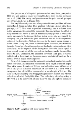
cott et al. [134]. The cavity configuration used for gain control, pumped
at 1480 nm, is shown in Figure 8.30.
The amplifier cavity contains a length of erbium-doped fiber with two
narrowband Bragg-matched fiber grating reflectors. Along with these
gratings, a STG filter with a specified intracavity, loss is included close
to the output end to control the intracavity loss and reduce the effect of
stray reflections. Above a certain threshold pump power at which the
cavity gain equals the intracavity loss, lasing occurs at a wavelength A l5
clamping the gain across the gain bandwidth due to the homogeneous
nature of the transition. With an increase in the pump power, energy is
stored in the lasing flux, while maintaining the inversion, and therefore
the gain. Signal wavelengths experience a fixed gain up to a certain critical
input level, at the expense of the lasing flux. Once the input signal is
large enough to extract all the energy from the lasing mode, the amplifier
ceases to lase. Thereafter, the amplifier inversion (and gain) is uncon-
trolled and is dependent on the pump power and signal levels as for a
normal erbium-doped fiber amplifier.
Figure 8.31 demonstrates the automatic optical gain controlled ampli-
fier in operation. The amplifier consists of a 25-m length of erbium-doped
fiber with a core diameter of 5.3 /um and refractive index difference of
0.013. The peak saturable absorption of the fiber is 6.1 dB/m with a
background loss of 8 dB/km measured at a wavelength of 1.1 yttm. The
laser cavity is defined by two Bragg grating reflectors at 1520 nm, written
in hydrogen-loaded GeO 2-SiO 2 fiber. The reflectivity of each grating is
94% with a 3-dB bandwidth of less than 0.4 nm. The splices dominate
Figure 8.30: Amplifier with linear optical AGC.