
Page 444 - Fiber Bragg Gratings
P. 444
9.3 Phase and temporal response of Bragg gratings 421
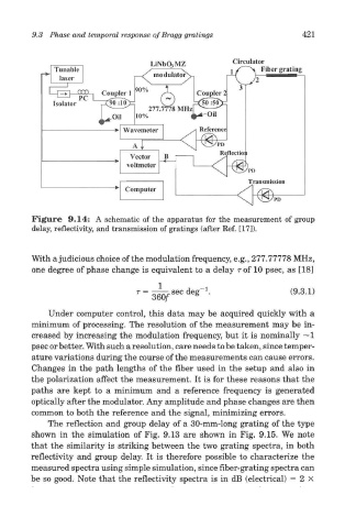
Figure 9.14: A schematic of the apparatus for the measurement of group
delay, reflectivity, and transmission of gratings (after Ref. [17]).
With a judicious choice of the modulation frequency, e.g., 277.77778 MHz,
one degree of phase change is equivalent to a delay r of 10 psec, as [18]
Under computer control, this data may be acquired quickly with a
minimum of processing. The resolution of the measurement may be in-
creased by increasing the modulation frequency, but it is nominally ~1
psec or better. With such a resolution, care needs to be taken, since temper-
ature variations during the course of the measurements can cause errors.
Changes in the path lengths of the fiber used in the setup and also in
the polarization affect the measurement. It is for these reasons that the
paths are kept to a minimum and a reference frequency is generated
optically after the modulator. Any amplitude and phase changes are then
common to both the reference and the signal, minimizing errors.
The reflection and group delay of a 30-mm-long grating of the type
shown in the simulation of Fig. 9.13 are shown in Fig. 9.15. We note
that the similarity is striking between the two grating spectra, in both
reflectivity and group delay. It is therefore possible to characterize the
measured spectra using simple simulation, since fiber-grating spectra can
be so good. Note that the reflectivity spectra is in dB (electrical) = 2 X