
Page 439 - Fiber Bragg Gratings
P. 439
416 Chapter 9 Measurement and Characterization of Gratings
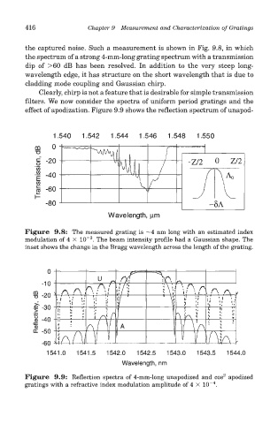
the captured noise. Such a measurement is shown in Fig. 9.8, in which
the spectrum of a strong 4-mm-long grating spectrum with a transmission
dip of >60 dB has been resolved. In addition to the very steep long-
wavelength edge, it has structure on the short wavelength that is due to
cladding mode coupling and Gaussian chirp.
Clearly, chirp is not a feature that is desirable for simple transmission
filters. We now consider the spectra of uniform period gratings and the
effect of apodization. Figure 9.9 shows the reflection spectrum of unapod-
Figure 9.8: The measured grating is ~4 nm long with an estimated index
3
modulation of 4 X 10~ . The beam intensity profile had a Gaussian shape. The
inset shows the change in the Bragg wavelength across the length of the grating.
2
Figure 9.9: Reflection spectra of 4-mm-long unapodized and cos apodized
4
gratings with a refractive index modulation amplitude of 4 x 10~ .