
Page 435 - Fiber Bragg Gratings
P. 435
412 Chapter 9 Measurement and Characterization of Gratings
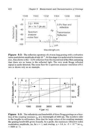
Figure 9.2: The reflection spectrum of a 4-mm-long grating with a refractive
7
index modulation amplitude of only 10~ . At this stage it is undetected in transmis-
sion. Also shown is the —3.5% reflection from the cleaved end of the fiber, assuming
that there are no losses in the reflected light. The very weak Bragg reflected
signal is easily detected. The noise floor for a spectrum analyzer resolution of 0.1
mm is shown only as an example.
Figure 9.3: The reflectivity and bandwidth of three Bragg gratings as a func-
tion of the coupling constant K OC at a wavelength of 1550 nm. The numbers refer
to the lengths in millimeters. Note that for large values of the coupling constant,
the grating bandwidth grows linearly. As a guide, the maximum refractive index
3
modulation amplitude, An, for v - 1, and overlap, 77 = 0.8, is ~3 X 10" (at K OC
1
= 5000 m" ).