
Page 89 - Fiber Bragg Gratings
P. 89
68 Chapter 3 Fabrication of Bragg Gratings
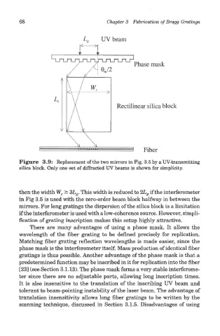
Figure 3.9: Replacement of the two mirrors in Fig. 3.5 by a UV-transmitting
silica block. Only one set of diffracted UV beams is shown for simplicity.
then the width W, ^ 3L P. This width is reduced to 2L ff if the interferometer
* 8 B
in Fig 3.5 is used with the zero-order beam block halfway in between the
mirrors. For long gratings the dispersion of the silica block is a limitation
if the interferometer is used with a low-coherence source. However, simpli-
fication of grating inscription makes this setup highly attractive.
There are many advantages of using a phase mask. It allows the
wavelength of the fiber grating to be defined precisely for replication.
Matching fiber grating reflection wavelengths is made easier, since the
phase mask is the interferometer itself. Mass production of identical fiber
gratings is thus possible. Another advantage of the phase mask is that a
predetermined function may be inscribed in it for replication into the fiber
[23] (see Section 3.1.13). The phase mask forms a very stable interferome-
ter since there are no adjustable parts, allowing long inscription times.
It is also insensitive to the translation of the inscribing UV beam and
tolerant to beam-pointing instability of the laser beam. The advantage of
translation insensitivity allows long fiber gratings to be written by the
scanning technique, discussed in Section 3.1.5. Disadvantages of using