
Page 85 - Fiber Bragg Gratings
P. 85
64 Chapters Fabrication of Bragg Gratings
Alternatively, the fiber may be placed directly behind the phase mask
for photo imprinting of the grating. In this scheme, there are two im-
portant issues. First, since the diffracted beams interfere in the region
of overlap immediately behind the phase mask, the fiber core needs to be
at the phase-mask surface for maximum overlap. The closest the phase
mask can be placed to a fiber core is a distance equal to the fiber radius
(unless a "D-fiber" is used), which means that there is no overlap of the
two beams in a short region at either end of the grating. Second, the
interference pattern generated at the fiber core is the sum of the interfer-
ence of all the diffracted orders. For a pure sinusoidal pattern at the fiber
core, it is important to allow only the two ± 1 orders to interfere with the
zero-order suppressed. As has been observed with the phase mask in
contact with the fiber, even with a zero-order nulled phase mask, the
period of the imprinted grating depends strongly on the intensity of the
writing UV beam. At low intensities, the period is half the phase-mask
period [see Eq. (3.1.3)], but at high intensities, even a low zero-order
intensity can interfere with the ±1 orders to create a grating of the same
period as the phase mask itself [120]. Tilting the fiber at an angle a behind
the phase mask so that one end is further away shifts the Bragg reflection
to longer wavelengths as the inverse of cosine a, since the fringe planes
are no longer orthogonal to the propagation axis. This method for tuning
the Bragg wavelength has been demonstrated [30]; it should, however,
be remembered that the grating length shortens with tilt, and not only
does the reflectivity drop (due to limited coherence of the UV source), but
radiation loss can increase [41] (see Section 3.1.4).
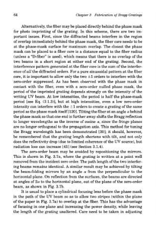
The zero-order beam may be avoided by repositioning the mirrors.
This is shown in Fig. 3.7a, where the grating is written at a point well
removed from the incident zero order. The path length of the two interfer-
ing beams remains identical. A similar result may be achieved by tilting
the beam-folding mirrors by an angle a from the perpendicular to the
horizontal plane. On reflection from the surfaces, the beams are directed
at angles of 2a to the horizontal plane, out of the plane of the zero-order
beam, as shown in Fig. 3.7b.
It is usual to place a cylindrical focusing lens before the phase mask
in the path of the UV beam so as to allow two stripes (within the plane
of the paper in Fig. 3.7a) to overlap at the fiber. This has the advantage
of focusing in one plane and increasing the power density, while leaving
the length of the grating unaltered. Care need to be taken in adjusting