
Page 80 - Fiber Bragg Gratings
P. 80
3.1 Methods for fiber Bragg grating fabrication 59
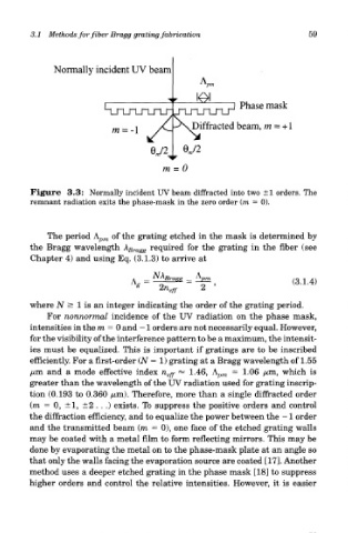
Figure 3.3: Normally incident UV beam diffracted into two ±1 orders. The
remnant radiation exits the phase-mask in the zero order (m = 0).
The period A pm of the grating etched in the mask is determined by
the Bragg wavelength A Bra^ required for the grating in the fiber (see
Chapter 4) and using Eq. (3.1.3) to arrive at
where N > 1 is an integer indicating the order of the grating period.
For nonnormal incidence of the UV radiation on the phase mask,
intensities in the m = 0 and — 1 orders are not necessarily equal. However,
for the visibility of the interference pattern to be a maximum, the intensit-
ies must be equalized. This is important if gratings are to be inscribed
efficiently. For a first-order (N — 1) grating at a Bragg wavelength of 1.55
/um and a mode effective index n eff *** 1.46, A p/n = 1.06 /ton, which is
greater than the wavelength of the UV radiation used for grating inscrip-
tion (0.193 to 0.360 /mi). Therefore, more than a single diffracted order
(m = 0, ±1, ±2 . . .) exists. To suppress the positive orders and control
the diffraction efficiency, and to equalize the power between the -1 order
and the transmitted beam (m = 0), one face of the etched grating walls
may be coated with a metal film to form reflecting mirrors. This may be
done by evaporating the metal on to the phase-mask plate at an angle so
that only the walls facing the evaporation source are coated [17]. Another
method uses a deeper etched grating in the phase mask [18] to suppress
higher orders and control the relative intensities. However, it is easier