
Page 77 - Fiber Bragg Gratings
P. 77
56 Chapter 3 Fabrication of Bragg Gratings
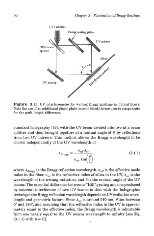
Figure 3.1: UV interferometer for writing Bragg gratings in optical fibers.
Note the use of an additional phase plate (mirror blank) in one arm to compensate
for the path length difference.
standard holography [16], with the UV beam divided into two at a beam
splitter and then brought together at a mutual angle of 0, by reflections
from two UV mirrors. This method allows the Bragg wavelength to be
chosen independently of the UV wavelength as
where A Smag. is the Bragg reflection wavelength, n e^is the effective mode
index in the fiber, n uv is the refractive index of silica in the UV, X uv is the
wavelength of the writing radiation, and 6 is the mutual angle of the UV
beams. The essential difference between a "Hill" grating and one produced
by external interference of two UV beams is that with the holographic
technique the Bragg reflection wavelength depends on UV radiation wave-
length and geometric factors. Since \ uv is around 240 nm, 6 lies between
0° and 180°, and assuming that the refractive index in the UV is approxi-
mately equal to the effective index, the Bragg wavelength is adjustable
from one nearly equal to the UV source wavelength to infinity [see Eq.
(3.1.1) with 0 = 0].