
Page 340 - Fiber Fracture
P. 340
322 C. Viney
c
0 Subunit in growing fibre 0 Previous nucleation site
Current nucleation site First subunit of new fibril
Fig. 8. Mechanism of collagen fibril growth in sea cucumber dermis and sea urchin ligament, based on
literature descriptions (Trotter et al., 1998, 2000a). The mechanism ensures a tapered shape and a consistent
axial ratio.
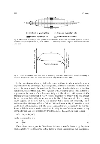
Fig. 9. Stress distributions associated with a reinforcing fibre in a more ductile matrix (according to
equations 6.40 (tensile stress) and 6.49 (shear stress) in Kelly and Macmillan, 1986).
In the case of conventional, cylindrical reinforcing fibres, the diameter is the same at
all points along the fibre length. If, as is expected, the fibres deform less readily than the
matrix, the shear stress in the matrix at the fibre-matrix interface is largest at the fibre
ends (see Kelly and Macmillan, 1986, equation 6.49), while the tensile stress in the fibre
is greatest at the middle of the fibre (see Kelly and Macmillan, 1986, equation 6.40).
These results are summarised in Fig. 9. Ideally, discontinuous fibres will be long enough
for the stress at their midpoint to approach the fibre failure strength. The necessary
length depends on the fibre radius, in a manner that is easily and commonly (Kelly
and Macmillan, 1986) quantified as follows. With reference to Fig. 10, consider a small
length dx of a fibre, near one end. The tensile stress in the fibre increases by do over this
distance. This increase in tensile stress is achieved by the interfacial shear stress t acting
on the interface area accommodated within the distance dx. A simple force balance
t(2nrdx) = do(nr2) (3)
can be rearranged to give
2t
do=-& (4)
r
If the failure stress o,,f of the fibres is reached over a transfer distance x,f, Eq. 4 can
be integrated between the corresponding limits to obtain an expression that incorporates