
Page 136 - Finite Element Analysis with ANSYS Workbench
P. 136
7.3 Academic Example 127
On DM window, set unit in the Units menu on the upper
tab to Meter.
On the Tree Outline window, right click on XYPlane and
select Look at. The X-Y-Z coordinates on the Model View
in 3D view will become X-Y coordinates in 2D view.
Select the Sketching tab below the Tree Outline window,
the Sketching Toolboxes will pop-up in the same place.
Select the Settings tab and then Grid, activate the buttons
Show in 2D and Snap. The grid will appear on the main
window in two dimensions. Grid snapping provides
convenience when drawing model.
Make sure that the Major Grid Spacing is set to 1 m,
Minor-Steps per Major is 1, and Snaps per Minor is 1.
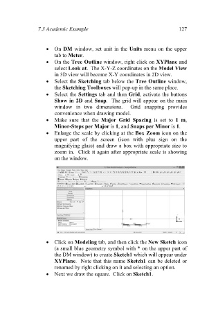
Enlarge the scale by clicking at the Box Zoom icon on the
upper part of the screen (icon with plus sign on the
magnifying glass) and draw a box with appropriate size to
zoom in. Click it again after appropriate scale is showing
on the window.
Click on Modeling tab, and then click the New Sketch icon
(a small blue geometry symbol with * on the upper part of
the DM window) to create Sketch1 which will appear under
XYPlane. Note that this name Sketch1 can be deleted or
renamed by right clicking on it and selecting an option.
Next we draw the square. Click on Sketch1.