
Page 137 - Finite Element Analysis with ANSYS Workbench
P. 137
128 Chapter 7 Vibration Analysis
Click the Sketching tab and select Draw. Choose Rectan-
gle to create the square with the vertices of (0,0) and (1,1).
This is done by clicking at the coordinates of (0,0) on the
model, move the cursor to the coordinates of (1,1) and click
the mouse again, the square domain will appear. Click on
Generate (the icon with yellow lightning on the upper-left
part of the screen). The desired square will pop up in dark
green.
The next important step is to go to the Concept tab on top
of the screen and select Surfaces From Sketches.
Select the Sketch1, the square will become yellow.
Click Apply icon on the right side of the Base Objects tab
in the Details View at the lower left of the screen. The
square will become cyan. The right side of the Base
Objects tab will show 1 Sketch.
Then, click on Generate. We now have the desired square
domain.
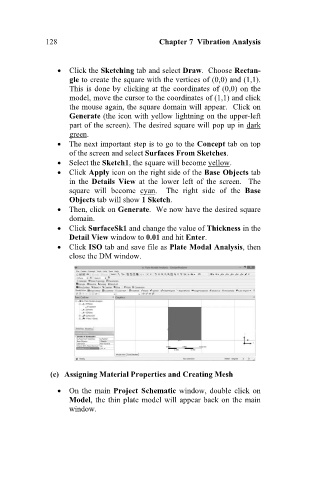
Click SurfaceSk1 and change the value of Thickness in the
Detail View window to 0.01 and hit Enter.
Click ISO tab and save file as Plate Modal Analysis, then
close the DM window.
(c) Assigning Material Properties and Creating Mesh
On the main Project Schematic window, double click on
Model, the thin plate model will appear back on the main
window.