
Page 165 - Finite Element Analysis with ANSYS Workbench
P. 165
156 Chapter 8 Failure Analysis
the DM window) to create Sketch1 which will appear under
XYPlane. Note that this name Sketch1 can be deleted or
renamed by right clicking on it and selecting an option.
Click on Sketch1, then click the Sketching tab and select
Draw.
Choose Line to create the lower line with the end
coordinates of (0,0) and (1,0). This is done by clicking the
mouse at the coordinates of (0,0) on the model, move the
cursor to the coordinates of (1,0), and click the mouse
again. Then, follow the same procedure to create all other
lines, and click Generate.
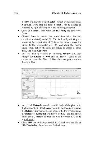
The left fillet is created by selecting Modify tab, then
change the Radius to 0.05 and hit Enter. Click at the
corner to create the fillet. Follow the same procedure for
the right fillet.
Next, click Extrude to make a solid body of the plate with
thickness of 0.02. Click Apply next to the Geometry under
the Details View window, and change the FD1 value under
the Details of Extrude1 window to be 0.02, and hit Enter.
Then, click Generate so that the plate becomes a 3D solid
in dark grey.
Click ISO tab to display model in 3D and save the file as
Life Prediction, then close the DM window.