
Page 163 - Finite Element Analysis with ANSYS Workbench
P. 163
154 Chapter 8 Failure Analysis
On the Analysis Systems window, click twice on the Static
Structural item. A new small box will appear on the
Project Schematic window.
Retype the name in the lower blue tab as the desired project
name, e.g., Life Prediction, and hit Enter.
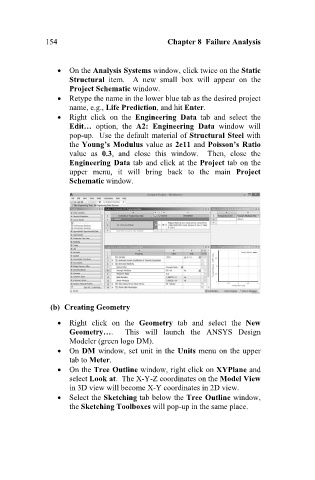
Right click on the Engineering Data tab and select the
Edit… option, the A2: Engineering Data window will
pop-up. Use the default material of Structural Steel with
the Young’s Modulus value as 2e11 and Poisson’s Ratio
value as 0.3, and close this window. Then, close the
Engineering Data tab and click at the Project tab on the
upper menu, it will bring back to the main Project
Schematic window.
(b) Creating Geometry
Right click on the Geometry tab and select the New
Geometry…. This will launch the ANSYS Design
Modeler (green logo DM).
On DM window, set unit in the Units menu on the upper
tab to Meter.
On the Tree Outline window, right click on XYPlane and
select Look at. The X-Y-Z coordinates on the Model View
in 3D view will become X-Y coordinates in 2D view.
Select the Sketching tab below the Tree Outline window,
the Sketching Toolboxes will pop-up in the same place.