
Page 158 - Finite Element Analysis with ANSYS Workbench
P. 158
8.1 Buckling 149
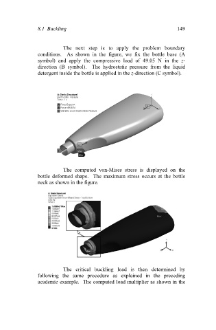
The next step is to apply the problem boundary
conditions. As shown in the figure, we fix the bottle base (A
symbol) and apply the compressive load of 49.05 N in the z-
direction (B symbol). The hydrostatic pressure from the liquid
detergent inside the bottle is applied in the z-direction (C symbol).
The computed von-Mises stress is displayed on the
bottle deformed shape. The maximum stress occurs at the bottle
neck as shown in the figure.
The critical buckling load is then determined by
following the same procedure as explained in the preceding
academic example. The computed load multiplier as shown in the