
Page 153 - Finite Element Analysis with ANSYS Workbench
P. 153
144 Chapter 8 Failure Analysis
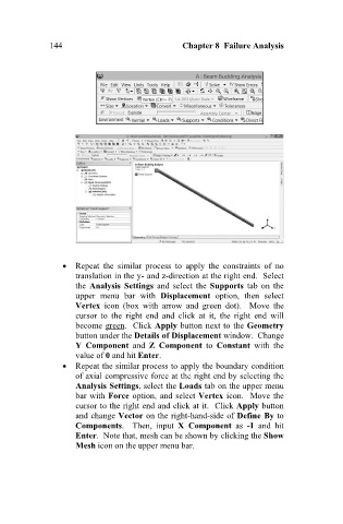
Repeat the similar process to apply the constraints of no
translation in the y- and z-direction at the right end. Select
the Analysis Settings and select the Supports tab on the
upper menu bar with Displacement option, then select
Vertex icon (box with arrow and green dot). Move the
cursor to the right end and click at it, the right end will
become green. Click Apply button next to the Geometry
button under the Details of Displacement window. Change
Y Component and Z Component to Constant with the
value of 0 and hit Enter.
Repeat the similar process to apply the boundary condition
of axial compressive force at the right end by selecting the
Analysis Settings, select the Loads tab on the upper menu
bar with Force option, and select Vertex icon. Move the
cursor to the right end and click at it. Click Apply button
and change Vector on the right-hand-side of Define By to
Components. Then, input X Component as -1 and hit
Enter. Note that, mesh can be shown by clicking the Show
Mesh icon on the upper menu bar.