
Page 152 - Finite Element Analysis with ANSYS Workbench
P. 152
8.1 Buckling 143
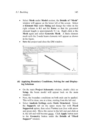
Select Mesh under Model section, the Details of “Mesh”
window will appear on the lower left of the screen. Select
at Element Size under Sizing and change the value on the
right column to 0.1 and hit Enter so that the generated
element length is approximately 0.1 m. Right click at the
Mesh again and select Generate Mesh. A finite element
mesh with the 2-node beam elements will appear as shown
in the figure.
Save the project and close the DM window.
(d) Applying Boundary Conditions, Solving for and Display-
ing Solutions
On the main Project Schematic window, double click on
Setup, the beam model will appear back on the main
window.
Next, the boundary conditions on both ends can be applied.
This will be done, one at a time, starting from the left end.
Select Analysis Settings under Static Structural. Select
the Supports tab on the upper menu bar with Fixed
Supported option, then select Vertex icon (box with arrow
and green dot). Move the cursor to the left end and click at
it, the left end will become green. Click Apply button next
to the Geometry button under the Details of “Fixed
Support” window.