
Page 148 - Finite Element Analysis with ANSYS Workbench
P. 148
8.1 Buckling 139
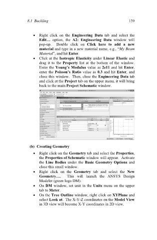
Right click on the Engineering Data tab and select the
Edit… option, the A2: Engineering Data window will
pop-up. Double click on Click here to add a new
material and type in a new material name, e.g., “My Beam
Material”, and hit Enter.
Click at the Isotropic Elasticity under Linear Elastic and
drag it to the Property list at the bottom of the window.
Enter the Young’s Modulus value as 2e11 and hit Enter,
enter the Poisson’s Ratio value as 0.3 and hit Enter, and
close this window. Then, close the Engineering Data tab
and click at the Project tab on the upper menu, it will bring
back to the main Project Schematic window.
(b) Creating Geometry
Right click on the Geometry tab and select the Properties,
the Properties of Schematic window will appear. Activate
the Line Bodies under the Basic Geometry Options and
close this small window.
Right click on the Geometry tab and select the New
Geometry…. This will launch the ANSYS Design
Modeler (green logo DM).
On DM window, set unit in the Units menu on the upper
tab to Meter.
On the Tree Outline window, right click on XYPlane and
select Look at. The X-Y-Z coordinates on the Model View
in 3D view will become X-Y coordinates in 2D view.