
Page 224 - Finite Element Analysis with ANSYS Workbench
P. 224
11.3 Academic Example 215
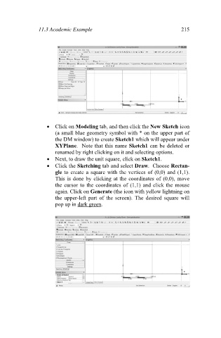
Click on Modeling tab, and then click the New Sketch icon
(a small blue geometry symbol with * on the upper part of
the DM window) to create Sketch1 which will appear under
XYPlane. Note that this name Sketch1 can be deleted or
renamed by right clicking on it and selecting options.
Next, to draw the unit square, click on Sketch1.
Click the Sketching tab and select Draw. Choose Rectan-
gle to create a square with the vertices of (0,0) and (1,1).
This is done by clicking at the coordinates of (0,0), move
the cursor to the coordinates of (1,1) and click the mouse
again. Click on Generate (the icon with yellow lightning on
the upper-left part of the screen). The desired square will
pop up in dark green.