
Page 225 - Finite Element Analysis with ANSYS Workbench
P. 225
216 Chapter 11 Incompressible Flow Analysis
The next important step is to go to the Concept tab on top
of the screen and select Surfaces From Sketches.
Select the Sketch1, the square will become yellow.
Click Apply icon on the right side of the Base Objects tab
in the Details View at the lower left of the screen. The
square will become cyan. The right side of the Base
Objects tab will show 1 Sketch with 1 Part, 1 Body
appears in the Tree Outline window.
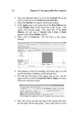
Then, click on Generate. We now have a unit square
domain.
The domain is ready for meshing, but before that, we will
specify boundary conditions on the domain first.
We will give the name of the upper edge as Lid. On the
upper tools bar, select the Selection Filter: Edges icon (box
with arrow and green edge)
Place the cursor near the top edge of the square and click,
the top edge will become green. Then, right click to select