
Page 261 - Finite Element Analysis with ANSYS Workbench
P. 261
252 Chapter 12 Compressible Flow Analysis
Computational
domain 1.4
2
2
R 287 m /sec -K
Bow shock .45 T 300 K
M 3
M=3 a 347.19 m/sec
u 1041.57 m/sec
3
1.18 kg/m
p 101598 N/m
2
.15 2 2
Cylinder c 1004.5 m /sec -K
p
Symmetry
.15 .15
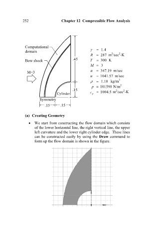
(a) Creating Geometry
We start from constructing the flow domain which consists
of the lower horizontal line, the right vertical line, the upper
left curvature and the lower right cylinder edge. These lines
can be constructed easily by using the Draw command to
form up the flow domain is shown in the figure.