
Page 262 - Finite Element Analysis with ANSYS Workbench
P. 262
12.3 Academic Example 253
Next, we assign the name for the upper left curvature and
the right vertical line as Farfield. We also assign the names
for the symmetrical line and cylinder edge as Symmetry
and Cylinder, respectively. These assigned names aid
application of the boundary conditions later.
(b) Generating Mesh
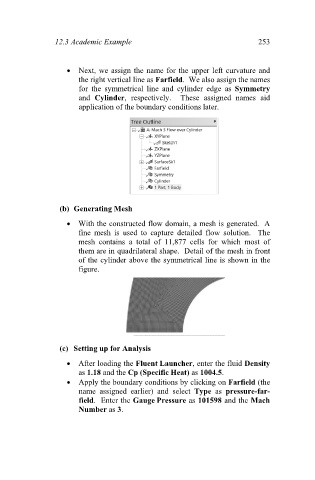
With the constructed flow domain, a mesh is generated. A
fine mesh is used to capture detailed flow solution. The
mesh contains a total of 11,877 cells for which most of
them are in quadrilateral shape. Detail of the mesh in front
of the cylinder above the symmetrical line is shown in the
figure.
(c) Setting up for Analysis
After loading the Fluent Launcher, enter the fluid Density
as 1.18 and the Cp (Specific Heat) as 1004.5.
Apply the boundary conditions by clicking on Farfield (the
name assigned earlier) and select Type as pressure-far-
field. Enter the Gauge Pressure as 101598 and the Mach
Number as 3.