
Page 81 - Finite Element Analysis with ANSYS Workbench
P. 81
72 Chapter 4 Plan Stress Analysis
(c) Assigning Material Properties and Creating Mesh
On the main Project Schematic window, double click on
Model, the solid plate model will appear back on the main
window.
Double click on Geometry item, the Surface Body item
will pop-up. Select the Surface Body item and select “My
Material” (the name assigned earlier containing material
properties of this problem) which is on the right-hand-side
of Assignment under Material in Details of “Surface
Body” window. The plate model will become green.
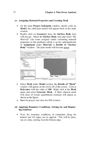
Select Mesh under Model section, the Details of “Mesh”
window will appear on the lower left of the screen. Click at
Relevance with the value of 100. Right click at the Mesh
again and select Generate Mesh. A finite element mesh
with most of 4-node quadrilateral elements will appear as
shown in the figure.
Save the project and close the DM window.
(d) Applying Boundary Conditions, Solving for and Display-
ing Solutions
Next, the boundary conditions of constraints along the
bottom and left edges can be applied. This will be done,
one at a time, starting from the bottom edge.