
Page 78 - Finite Element Analysis with ANSYS Workbench
P. 78
4.3 Academic Example 69
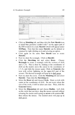
Click on Modeling tab, and then click the New Sketch icon
(a small blue geometry symbol with * on the upper part of
the DM window) to create Sketch1 which will appear under
XYPlane. Note that this name Sketch1 can be deleted or
renamed by right clicking on it and selecting an option.
Click again on the same New Sketch icon to create
Sketch2.
Next we draw the rectangle. Click on Sketch1.
Click the Sketching tab and select Draw. Choose
Rectangle to create a rectangle with the vertices of (0,0)
and (.7,.5). This is done by clicking at the coordinates of
(0,0) on the model, move the cursor to the coordinates of
(.7,.5), and click the mouse again. Click on Generate (the
icon with yellow lightning on the upper-left part of the
screen). The desired rectangle will pop up in dark green.
Next we draw the circle. Click the Modeling tab and select
Sketch2. Then click the Sketching tab.
Select the Draw tab and choose Circle. Draw a circle with
center at the coordinates of (0,0). Do not worry about the
size of the circle, it will be taken care later. Then, click the
Generate button.
Select the Dimensions tab and choose Radius. Left click
on the circle that just drew, drag the mouse outward without
releasing the mouse until seeing an arrow with notation R1,
then release the mouse. The desired circle will pop up in
dark green.