
Page 159 - Finite Element Modeling and Simulations with ANSYS Workbench
P. 159
144 Finite Element Modeling and Simulation with ANSYS Workbench
and Ø as 12mm as shown below. When entering values for the Ø and Sides of
the polygon, press the Tab key to switch between the Ø and Sides boxes for
data entry. Here Ø represents the diameter of inscribed circle of the polygon.
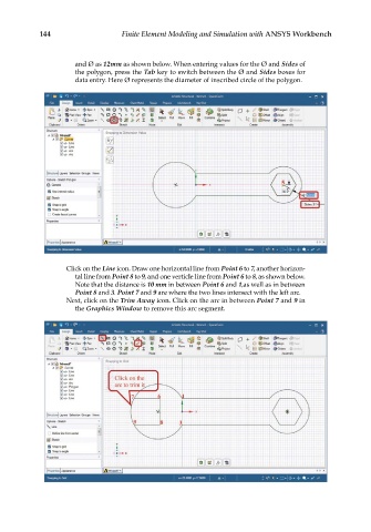
Click on the Line icon. Draw one horizontal line from Point 6 to 7, another horizon-
tal line from Point 8 to 9, and one verticle line from Point 6 to 8, as shown below.
Note that the distance is 10 mm in between Point 6 and 1,as well as in between
Point 8 and 3. Point 7 and 9 are where the two lines intersect with the left arc.
Next, click on the Trim Away icon. Click on the arc in between Point 7 and 9 in
the Graphics Window to remove this arc segment.