
Page 190 - Finite Element Modeling and Simulations with ANSYS Workbench
P. 190
Modeling and Solution Techniques 175
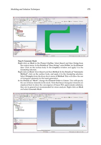
Step 8: Generate Mesh
Right click on Mesh in the Project Outline. Select Insert and then Sizing from
the context menu. In the Details of “Face Sizing”, enter’0.03m’ for the Element
Size. Click on the surface body in the Graphics window and apply it to the
Geometry selection.
Right click on Mesh. Select Insert and then Method. In the Details of “Automatic
Method”, click on the surface body, and apply it to the Geometry selection.
Select Triangles from the drop-down menu of Method. This will allow the use
of triangular elements for the mesh generation.
In the Details of “Mesh”, change the Element Order to Linear. This will specify
the use of linear elements in the mesh. Note that linear triangular elements are
employed here to show the convergence of linear FEA approximate solutions;
they are in general not recommended for stress analysis. Right-click on Mesh
and select Generate Mesh.