
Page 191 - Finite Element Modeling and Simulations with ANSYS Workbench
P. 191
176 Finite Element Modeling and Simulation with ANSYS Workbench
Step 9: Apply Boundary Conditions
Right-click on Static Structural (A5). Choose Insert and then Fixed Support
from the context menu. Apply this support to the horizontal line at the
bottom.
Right-click on Static Structural (A5). Choose Insert and then Frictionless Support
from the context menu. Apply this support to the leftmost vertical line (center line
of the fountain). The frictionless support prevents the line from moving or deform-
ing in the normal direction, and thus is equivalent to a symmetry condition.
Step 10: Apply Loads
In the Project Outline, right-click on Static Structural (A5). Choose Insert and
then Hydrostatic Pressure. The hydrostatic load simulates pressure due to
fluid weight.
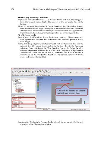
In the Details of “Hydrostatic Pressure”, ctrl-click the horizontal line and the
adjacent line fillet shown below, and apply the two edges to the Geometry
selection. Enter 1000 kg/m for Fluid Density. Change the Define By selec-
3
tion to Components, and enter 9.8 m/s for the Y Component of Hydrostatic
2
Acceleration. Enter 0.68 m for the X Coordinate and 0.76 m for the Y
Coordinate for the Free Surface Location. The location corresponds to the
upper endpoint of the line fillet.
Insert another Hydrostatic Pressure load, and apply the pressure to the line and
the adjacent line fillet as shown below.