
Page 383 - Finite Element Modeling and Simulations with ANSYS Workbench
P. 383
368 Finite Element Modeling and Simulation with ANSYS Workbench
10.5 Summary
In this chapter, we briefly discussed the governing equations in fluid dynamics, main
variables of concern, boundary conditions, and procedures in conducting CFD model-
ing and analysis. A case study using ANSYS Workbench is demonstrated using a truck
model.
10.6 Review of Learning Objectives
Now that you have finished this chapter you should be able to
1. Understand the unique nature of fluid dynamics problems, including its govern-
ing equations, variables, and boundary conditions
2. Know how to create quality mesh for CFD analysis
3. Know how to apply the boundary conditions for CFD analysis
4. Perform CFD modeling and analysis of flows in complex domains using ANSYS
Workbench
PROBLEMS
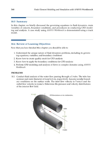
10.1 Conduct fluid analysis of the water flow passing through a U-tube. The tube has
an inner and outer diameter of 4 and 4.2 cm, respectively. Assume nonslip bound-
ary conditions on the surface walls. The inlet flow velocity is 5 mm/s and the
outlet flow velocity is 4 mm/s. Determine the pressure and velocity distributions
of the interior flow field.
R5.000 All dimensions are in centimeters.
Inlet
10.000
10.000
Outlet