
Page 398 - Finite Element Modeling and Simulations with ANSYS Workbench
P. 398
Design Optimization 383
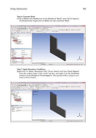
Step 6: Generate Mesh
Click on Mesh in the Outline tree. In the Details of “Mesh”, enter’1.0’ for 1mm for
the Element Size. Right-click on Mesh and select Generate Mesh.
Step 7: Apply Boundary Conditions
Right-click on Static Structural (A5). Choose Insert and then Fixed Support
from the context menu. Click on the top face, and apply it to the Geometry
selection in the Details of “Fixed Support”. The top face of the L-shape is now
fixed as shown below.