
Page 324 - Flexible Robotics in Medicine
P. 324
314 Chapter 13
As canbeseenfromthe image onthe left of Fig. 13.28, the flexible tip of the device
was attached to a specially fabricated block, which allowed for the device to be easily
grasped by the pneumatic claw of the Instron. The other pneumatic claw was then used
to grasp a length of nylon, which had been threaded through the length of the flexible
tip. As the Instron pulled the nylon thread, it would cause the flexible tip to bend, as
can be observed in the image on the right. This would continue until the flexible tip
fractured or failed under stress. The stress at which this failure occurred would then be
recorded. The same analysis was also done on the nylon thread alone. The results for
mechanical analysis verification of nylon as well as Prototypes 5.0 7.0 are detailed in
Figs. 13.27 13.30, along with the relevant conclusions derived from results in
(Figs. 13.31 and 13.32).
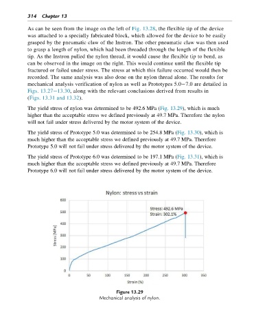
The yield stress of nylon was determined to be 492.6 MPa (Fig. 13.29), which is much
higher than the acceptable stress we defined previously at 49.7 MPa. Therefore the nylon
will not fail under stress delivered by the motor system of the device.
The yield stress of Prototype 5.0 was determined to be 254.8 MPa (Fig. 13.30), which is
much higher than the acceptable stress we defined previously at 49.7 MPa. Therefore
Prototype 5.0 will not fail under stress delivered by the motor system of the device.
The yield stress of Prototype 6.0 was determined to be 197.1 MPa (Fig. 13.31), which is
much higher than the acceptable stress we defined previously at 49.7 MPa. Therefore
Prototype 6.0 will not fail under stress delivered by the motor system of the device.
Figure 13.29
Mechanical analysis of nylon.