
Page 379 - Flexible Robotics in Medicine
P. 379
372 Chapter 16
Figure 16.8
The red wire is pulled when servo motor rotates, while the green wire is slackened. The camera
ring is tilted.
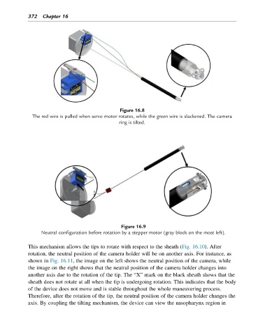
Figure 16.9
Neutral configuration before rotation by a stepper motor (gray block on the most left).
This mechanism allows the tips to rotate with respect to the sheath (Fig. 16.10). After
rotation, the neutral position of the camera holder will be on another axis. For instance, as
shown in Fig. 16.11, the image on the left shows the neutral position of the camera, while
the image on the right shows that the neutral position of the camera holder changes into
another axis due to the rotation of the tip. The “X” mark on the black sheath shows that the
sheath does not rotate at all when the tip is undergoing rotation. This indicates that the body
of the device does not move and is stable throughout the whole maneuvering process.
Therefore, after the rotation of the tip, the neutral position of the camera holder changes the
axis. By coupling the tilting mechanism, the device can view the nasopharynx region in