
Page 375 - Flexible Robotics in Medicine
P. 375
368 Chapter 16
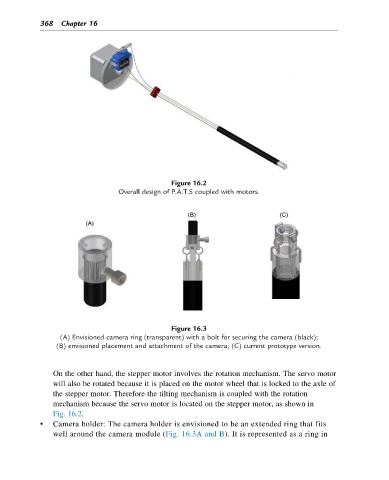
Figure 16.2
Overall design of P.A.T.S coupled with motors.
Figure 16.3
(A) Envisioned camera ring (transparent) with a bolt for securing the camera (black);
(B) envisioned placement and attachment of the camera; (C) current prototype version.
On the other hand, the stepper motor involves the rotation mechanism. The servo motor
will also be rotated because it is placed on the motor wheel that is locked to the axle of
the stepper motor. Therefore the tilting mechanism is coupled with the rotation
mechanism because the servo motor is located on the stepper motor, as shown in
Fig. 16.2.
• Cameraholder: Thecameraholderisenvisionedtobeanextendedringthatfits
well around the camera module (Fig. 16.3A and B). It is represented as a ring in