
Page 376 - Flexible Robotics in Medicine
P. 376
Robotic transluminal Pan-and-Tilt Scope 369
the current device stage (Fig. 16.3C) without the actual camera module. The ring
has four holes: two for the ring to be mounted on the tip of the scope with metal
pins, and two to be threaded by string or wires that control the tilting motion of
the ring.
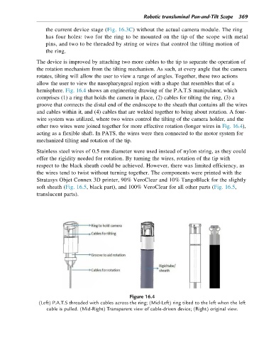
The device is improved by attaching two more cables to the tip to separate the operation of
the rotation mechanism from the tilting mechanism. As such, at every angle that the camera
rotates, tilting will allow the user to view a range of angles. Together, these two actions
allow the user to view the nasopharyngeal region with a shape that resembles that of a
hemisphere. Fig. 16.4 shows an engineering drawing of the P.A.T.S manipulator, which
comprises (1) a ring that holds the camera in place, (2) cables for tilting the ring, (3) a
groove that connects the distal end of the endoscope to the sheath that contains all the wires
and cables within it, and (4) cables that are welded together to bring about rotation. A four-
wire system was utilized, where two wires control the tilting of the camera holder, and the
other two wires were joined together for more effective rotation (longer wires in Fig. 16.4),
acting as a flexible shaft. In PATS, the wires were then connected to the motor system for
mechanized tilting and rotation of the tip.
Stainless steel wires of 0.5 mm diameter were used instead of nylon string, as they could
offer the rigidity needed for rotation. By turning the wires, rotation of the tip with
respect to the black sheath could be achieved. However, there was limited efficiency, as
the wires tend to twist without turning together. The components were printed with the
Stratasys Objet Connex 3D printer, 90% VeroClear and 10% TangoBlack for the slightly
soft sheath (Fig. 16.5, black part), and 100% VeroClear for all other parts (Fig. 16.5,
translucent parts).
Figure 16.4
(Left) P.A.T.S threaded with cables across the ring; (Mid-Left) ring tilted to the left when the left
cable is pulled. (Mid-Right) Transparent view of cable-driven device; (Right) original view.