
Page 44 - Fluid Mechanics and Thermodynamics of Turbomachinery
P. 44
Basic Thermodynamics, Fluid Mechanics: Definitions of Efficiency 25
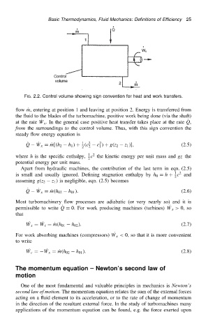
FIG. 2.2. Control volume showing sign convention for heat and work transfers.
flow Pm, entering at position 1 and leaving at position 2. Energy is transferred from
the fluid to the blades of the turbomachine, positive work being done (via the shaft)
P
at the rate P W x . In the general case positive heat transfer takes place at the rate Q,
from the surroundings to the control volume. Thus, with this sign convention the
steady flow energy equation is
2
P
1
Q P W x DPm[.h 2 h 1 / C .c 2 c / C g.z 2 z 1 /], (2.5)
2 2 1
1 2
where h is the specific enthalpy, c the kinetic energy per unit mass and gz the
2
potential energy per unit mass.
Apart from hydraulic machines, the contribution of the last term in eqn. (2.5)
1 2
is small and usually ignored. Defining stagnation enthalpy by h 0 D h C c and
2
assuming g.z 2 z 1 / is negligible, eqn. (2.5) becomes
P
Q W x h 01 /. (2.6)
P DPm.h 02
Most turbomachinery flow processes are adiabatic (or very nearly so) and it is
P
permissible to write Q D 0. For work producing machines (turbines) P W x > 0, so
that
P W x D P W t DPm.h 01 h 02 /. (2.7)
For work absorbing machines (compressors) P W x < 0, so that it is more convenient
to write
P W c D P W x DPm.h 02 h 01 /. (2.8)
The momentum equation Newton’s second law of
motion
One of the most fundamental and valuable principles in mechanics is Newton’s
second law of motion. The momentum equation relates the sum of the external forces
acting on a fluid element to its acceleration, or to the rate of change of momentum
in the direction of the resultant external force. In the study of turbomachines many
applications of the momentum equation can be found, e.g. the force exerted upon