Page 59 - Fluid Mechanics and Thermodynamics of Turbomachinery
P. 59

40 Fluid Mechanics, Thermodynamics of Turbomachinery
                          Reheat factor

                            The foregoing relations obviously cannot be applied to steam turbines as vapours
                          do not in general obey the gas laws. It is customary in steam turbine practice to
                          use a reheat factor R H as a measure of the inefficiency of the complete expansion.
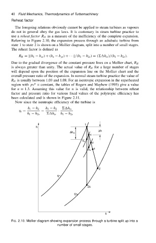
                          Referring to Figure 2.10, the expansion process through an adiabatic turbine from
                          state 1 to state 2 is shown on a Mollier diagram, split into a number of small stages.
                          The reheat factor is defined as

                              R H D [.h 1  h xs / C .h x  h ys / C ÐÐÐ]/.h 1  h 2s / D .h is //.h 1  h 2s /.
                          Due to the gradual divergence of the constant pressure lines on a Mollier chart, R H
                          is always greater than unity. The actual value of R H for a large number of stages
                          will depend upon the position of the expansion line on the Mollier chart and the
                          overall pressure ratio of the expansion. In normal steam turbine practice the value of
                          R H is usually between 1.03 and 1.08. For an isentropic expansion in the superheated
                                      n
                          region with pv = constant, the tables of Rogers and Mayhew (1995) give a value
                          for n D 1.3. Assuming this value for n is valid, the relationship between reheat
                          factor and pressure ratio for various fixed values of the polytropic efficiency has
                          been calculated and is shown in Figure 2.11.
                            Now since the isentropic efficiency of the turbine is
                                   h 1  h 2  h 1  h 2  h is
                                t D       D        Ð
                                   h 1  h 2s  h is  h 1  h 2s


                                                                  1
                                       h
                                                                         Dh
                                                          Dh is
                                                                     x
                                                                x s
                                                                      y
                                                                    y s  z


                                                                         2
                                                   p  1


                                                                   2s
                                                            p  2


                                                                             s
                          FIG. 2.10. Mollier diagram showing expansion process through a turbine split up into a
                                                   number of small stages.
   54   55   56   57   58   59   60   61   62   63   64