Page 61 - Fluid Mechanics and Thermodynamics of Turbomachinery
P. 61

42 Fluid Mechanics, Thermodynamics of Turbomachinery
                                       h                               P 1

                                                            01  02

                                                                                 P 2
                                                   1  2
                                                     C 1
                                                   2
                                                              1      1
                                            1  2                      C 2 2
                                            2  C 2s                  2


                                                                 2
                                                             2s


                                     (a)                                  s


                                                         01       02
                                       h
                                                                        1  C 2 2
                                                     P 01   P 02  2     2


                                                        2s                       1  2
                                                                                 2  C 1


                                                  P 2


                                                           1
                                                     P 1

                                                                           s
                                     (b)
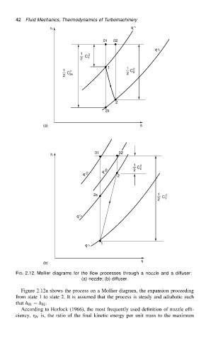
                          FIG. 2.12. Mollier diagrams for the flow processes through a nozzle and a diffuser:
                                                   (a) nozzle; (b) diffuser.

                            Figure 2.12a shows the process on a Mollier diagram, the expansion proceeding
                          from state 1 to state 2. It is assumed that the process is steady and adiabatic such
                          that h 01 D h 02 .
                            According to Horlock (1966), the most frequently used definition of nozzle effi-
                          ciency,   N is, the ratio of the final kinetic energy per unit mass to the maximum
   56   57   58   59   60   61   62   63   64   65   66