
Page 66 - Fluid Mechanics and Thermodynamics of Turbomachinery
P. 66
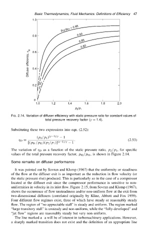
Basic Thermodynamics, Fluid Mechanics: Definitions of Efficiency  47
                                      1.0
                                                     p 02 /p 01  =  0.95


                                      0.8                     0.90
                                                               0.85
                                                                0.80
                                   Diffuser efficiency, h D  0.4
                                      0.6


                                      0.2


                                      0
                                       1.0      1.2      1.4      1.6      1.8      2.0
                                                             p /p 1
                                                              2
                          FIG. 2.14. Variation of diffuser efficiency with static pressure ratio for constant values of
                                             total pressure recovery factor (
 D 1.4).


                          Substituting these two expressions into eqn. (2.52):
                                        .p 2 /p 1 / .
 1//
  1
                                D D                          .                            (2.53)
                                   [.p 01 /p 02 /.p 2 /p 1 /] .
 1//
  1

                          The variation of   D as a function of the static pressure ratio, p 2 /p 1 , for specific
                          values of the total pressure recovery factor, p 02 /p 01 , is shown in Figure 2.14.

                          Some remarks on diffuser performance

                            It was pointed out by Sovran and Klomp (1967) that the uniformity or steadiness
                          of the flow at the diffuser exit is as important as the reduction in flow velocity (or
                          the static pressure rise) produced. This is particularly so in the case of a compressor
                          located at the diffuser exit since the compressor performance is sensitive to non-
                          uniformities in velocity in its inlet flow. Figure 2.15, from Sovran and Klomp (1967),
                          shows the occurrence of flow unsteadiness and/or non-uniform flow at the exit from
                          two-dimensional diffusers (correlated originally by Kline, Abbott and Fox 1959).
                          Four different flow regimes exist, three of which have steady or reasonably steady
                          flow. The region of “no appreciable stall” is steady and uniform. The region marked
                          “large transitory stall” is unsteady and non-uniform, while the “fully-developed” and
                          “jet flow” regions are reasonably steady but very non-uniform.
                            The line marked a a will be of interest in turbomachinery applications. However,
                          a sharply marked transition does not exist and the definition of an appropriate line