
Page 70 - Fluid Mechanics and Thermodynamics of Turbomachinery
P. 70
Basic Thermodynamics, Fluid Mechanics: Definitions of Efficiency 51
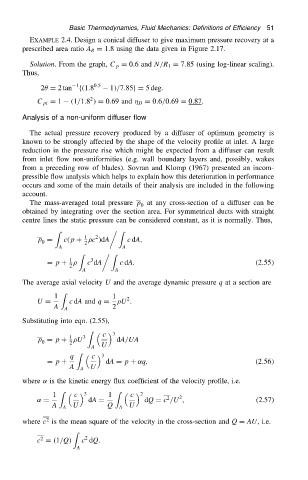
EXAMPLE 2.4. Design a conical diffuser to give maximum pressure recovery at a
prescribed area ratio A R D 1.8 using the data given in Figure 2.17.
Solution. From the graph, C p D 0.6 and N/R 1 D 7.85 (using log-linear scaling).
Thus,
1
2 D 2 tan f.1.8 0.5 1//7.85gD 5 deg.
2
C pi D 1 .1/1.8 / D 0.69 and D D 0.6/0.69 D 0.87.
Analysis of a non-uniform diffuser flow
The actual pressure recovery produced by a diffuser of optimum geometry is
known to be strongly affected by the shape of the velocity profile at inlet. A large
reduction in the pressure rise which might be expected from a diffuser can result
from inlet flow non-uniformities (e.g. wall boundary layers and, possibly, wakes
from a preceding row of blades). Sovran and Klomp (1967) presented an incom-
pressible flow analysis which helps to explain how this deterioration in performance
occurs and some of the main details of their analysis are included in the following
account.
The mass-averaged total pressure p at any cross-section of a diffuser can be
0
obtained by integrating over the section area. For symmetrical ducts with straight
centre lines the static pressure can be considered constant, as it is normally. Thus,
Z Z
2
1
p D c.p C c /dA c dA,
0 2
A A
Z Z
3
1
D p C c dA c dA. .2.55/
2
A A
The average axial velocity U and the average dynamic pressure q at a section are
Z
1 1 2
U D c dA and q D U .
A A 2
Substituting into eqn. (2.55),
Z
c 3
1
p D p C U 3 dA/UA
0
2
A U
q Z c 3
D p C dA D p C ˛q, .2.56/
A A U
where ˛ is the kinetic energy flux coefficient of the velocity profile, i.e.
Z Z
1 c 3 1 c 2 2
2
˛ D dA D dQ D c /U , (2.57)
A A U Q A U
2
where c is the mean square of the velocity in the cross-section and Q D AU, i.e.
Z
2
2
c D .1/Q/ c dQ.
A